 SAIL MAKING - Sail Sape
by
Ben Morris
(last edited 08/06/2021)
Sail Shape
Sail Twist
Sail Design
Sail Curvature
Built in Shape
Built in shape is
essential if the leech of the sail is to hold up and allow draught or curvature
right to the head. Single panel sails fail miserably here and invariably
allow the top half of the sail to fall off and provide little drive. This
is often evident by a diagonal crease across the sail. The degree of
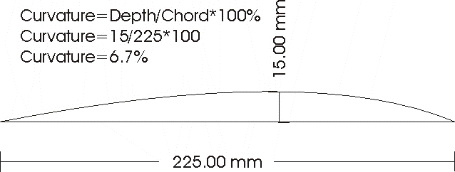
curvature suggested by various texts varies but values between 6% and 14% seem
to be the range which most sail-makers use.

In
addition it would seem that the curvature should increase as the chord decreases
so that for a normal sail the foot might have a curvature of say 6% increasing
to say 10% at the head. There are very good reasons for this.
Twist in Sails
The main
reason for this is the need to keep all of the sail working and not stalling
which results in drag. Telltales on the leech of a mainsail will reveal
this by curving around the sail and blowing forward on the windward side.
The interaction of the jib in forcing the wind to a higher angle of attack lower
in the mainsail accentuates the need to have twist
Twist in
the sail is also required because of the wind gradient up the sail. Because of
the friction between the water surface and the air, the velocity of the wind
increases the further we are from the surface. The head of the sail is in
a greater wind speed than the foot.. This is particularly significant in
lighter winds. As the wind increases the apparent wind moves outboard
requiring twist to keep its angle of attack to the wind the same and so prevent
stalling
Aerodynamic
theory predicts that with a shorter chord as found near the head, the sail is
more likely to stall (read about Reynolds number) so to overcome this more twist
is needed whereby the top part of the sail is twisted further away
from the centre line of the boat. If close hauled the foot may make an
angle of 5 degrees to the line of the boat but the top of the sail may make an
angle of 20degrees.

This
certainly prevents the top of the sail stalling but it stops it working too as
its chord line may well be close to the wind direction. To avoid this more
draught or curvature is added giving more 'lift' to increase the drive so all
parts of the sail are working effectively.
Where to Start - Sail Design
Like all good theories
there seems to be a lot of trial and error in achieving the desired outcome.
So it is with sail making. I suppose there are so many variables in
achieving an efficient sail that the only way I found to to start was to decide
on a set of specifications that seem to be an integration of all the best
aspects of sails you can read about or observe. Then vary them to see what
works and what doesn't.
To begin with all of the
sails I made were for Marblehead yachts so many of the variables are fixed.
For an 'A' rig, maximum luff height, amount and position of roach on the leech
and consequently foot measurement are basically determined within a fairly
narrow range. The sail dimensions at the 1/4, 1/2 and 3/4 positions are
also more or less determined as well. There are a maximum of 4 battens
evenly spread up the leech so it made sense to me then to make a sail with five
panels with a batten at each panel join. I chose this in favour of the
other common arrangement where only 3 battens are used at the 1/4, 1/2 and 3/4
points and only 4 panels used for the sail. My thinking was that only
three panel seams would not allow for as smooth a curve to be generated
lengthwise as four seams. For a jib with it's shorter luff, I use a four
panel sail for a Marblehead with three battens on the 1/3, 1/2 and 3/4 positions
matching the seams. One metre design almost defines the panels as four and
three for main and jib and allows battens at the seams.
Decide on the type of
Curvature
I started by deciding on
what type of curve to use and the point of maximum draft. Having a
background knowledge of airfoils commonly used in model gliders I decided that
a parabolic curve would generate more lift than a circular section. This
has the slight disadvantage of having a greater angle of attack to the incoming
wind but this is certainly no issue with wings where the aerofoil is angled much
closer to the wind direction than a yacht sail. I searched the NACA
airfoils for one of about 15% thickness and max thickness of near 35-40% of
chord. Then I changed the front curve to a extend to a point to match the
curve of a sail as they do not
have a solid section with such a rounded entry. (Perhaps the mast can serve as this)
-
Profile NACA 642-015 (642-015A has max thickness at
40%)
-
Max Thickness 15% so for ½ is 7.5% (6.85% including
extra 2cm)
-
Thickness at 35% on airfoil so on flat curve with 2cms
extra length is 40%
-
Chord used is 450mm but becomes 470mm by continuing
curve to origin


I have
since decided to use some of the information on Lester Gilbert's site and
created a parabolic curve with the maximum draft at 43% of the chord. I
think this is a better compromise with the maximum draft a little further back
to enable a slightly sharper entry. This should give better pointing
without detracting from its power off the wind. See the
spreadsheet for details.